Iranian Classification Society Rules

< Previous | Contents | Next >
Section 2 Stability
201.
1.
General
Intact stability is to be in accordance with this section in addition to the relevant requirement of
Ch 3, Sec 1. However, for ships specifically approved by the Society, these requirements may be
![]()
waived.
2. Stability to be considered especially to the ships that have specially designated operations.
3. The submission of evidence showing approval by an Administration of stability of the vessel for the lifting operations in accordance with a recognized standard may be accepted.
4. The dynamic load chart for each crane shall be included in the Trim and Stability Booklet and shall be posted at the crane operator's station in the clear view of the crane operator.
202. Calculation on stability
In applying the requirements in Pt 1, Annex 1-2 of Rules for the Classification
of Steel
Ships, the heeling lever resulting from designated operations is to be considered the most un- favorable for stability.
203.
Intact Stability Requirements for Vessels Equipped to Lift
1. Stability Information
(1) Specific Applicability
This appendix applies to each vessel that:
(a) Is equipped for heavy lifting of cargo or other objects; and
(b) Has a maximum heeling moment due to hook load greater than or equal to:
ÓThŅÑ∆ÀC ÕÄŤhÆ P
where:
(m-tons)
∆ = displacement of the vessel with the hook load included (tons)
ÀC = metacentric height with hook load included (m)
Ä = freeboard to the deck edge amidships (m)
Æ = beam (m)
(2) Definition
As used in this requirement.
(a) “Hook load” means the weight of the object lifted by the crane.
(b) “Load radius” means the distance illustrated in Fig 6.1.
(c)
“Crane Heeling Moment” is the maximum heeling moment developed by multiplying the weight of the hook load and boom by the horizontal distance from vessel’s centerline to the hook load and boom center of gravity, considering the full range of crane elevations and weights. The resulting heeling moment is to be converted to a heeling arm at zero degrees by dividing it by the vessel displacement. The heeling arm is to be assumed constant for all heel angles.
(d) “Equilibrium heel angle” is the angle of heel under the combined effects of the hook load, counter-ballasting and a beam wind.
2. Intact Stability Requirements for Vessels Equipped to Lift
(1) Counter-ballasted and Non-counter-ballasted Vessels
(A) Each vessel that is equipped to lift is to comply, by design calculations, with this section under the following conditions:
(a) Either for each loading condition(see Ch 3, 102.) and pre-lift condition, or the range of conditions, including pre-lift conditions, delineated by the lifting operations guidelines
contained in the trim and stability booklet; and
(b) Crane Heeling Moment, and
(c) The effect of beam wind on the projected area of the vessel (including deck cargo)
should be evaluated for 25.7 m/s (50 knots) wind speed. Should a lesser wind speed be used, that wind speed shall be listed in the trim and stability booklet as an operational restriction during lifting operations.
The wind heeling moment shall be calculated as:
Ç × A × Ā
where
(N-m)
Ç = wind pressure, calculated as per below
A = projected lateral area (m2), of all exposed surfaces (including deck cargo), in the up-
right condition
Ā = vertical distance (m), from the center of A to the center of the underwater lateral area
30 Guidance for Offshore Support Vessels 2015
![]()
or approximately to the one-half draft point
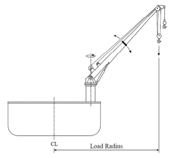
Fig 6.1 Load Radius
This wind heeling moment is to remain constant for all heel angles.
Č Ņ ᾚĐ
where
Ǽ
Ǽ
Ī
ᾟ ᾯ ᾜ
(N/m2 )
ᾚ = 0.611
Đᾟ = wind velocity (m/s)
Ǽᾯ = 1.0, shape coefficient
Ǽᾜ = height coefficient from Table 6.1
Table 6.1 Ch Value
À (m) | Ǽᾜ |
0.0 - 15.3 | 1.00 |
15.3 - 30.5 | 1.10 |
30.5 - 46.0 | 1.20 |
46.0 - 61.0 | 1.30 |
61.0 - 76.0 | 1.37 |
76.0 - 91.5 | 1.43 |
91.5 above | 1.48 |
(B) Each vessel is to have a righting arm curve with the following characteristics:
(a) The area under the righting arm curve from the equilibrium heel angle (based upon the wind heeling moment) up to the smallest of the following angles must be at least 0.080 meter-radians :
(i) The second intercept
(ii) The downflooding angle
(iii) 40 degrees
(b) The lowest portion of the weather deck and downflooding point should not be sub- merged at the equilibrium heel angle.
(c) The heeling angle based on the crane heeling moment and effect of the beam wind
shall not exceed the maximum heel angle from the crane manufacturer.
The righting arm curve is to be corrected for the increase in the vertical center of gravity due to the lifting operation. (The increase in the VCG is due to the boom being in the ele-
Guidance for Offshore Support Vessels 2015 31
![]()
vated position, and the hook load acting at the elevated end of the boom.).
(2) Additional Intact Stability Standards – Counter-ballasted Vessels
The following recommended criteria are based on crane operations taking place in favorable weather conditions. The analysis should be carried out for the counter-ballast case when the ves- sel is floating with a heel and trim not exceeding the maximum cross angle. The maximum cross angle is the angle corresponding to the crane operational restrictions.
The righting arm curve is to be corrected for the increase in the vertical center of gravity due to the load. (The increase in the VCG is due to the boom being in the elevated position, and the hook load acting at the elevated end of the boom.).
(a) For any condition of loading and crane heeling moment, the first intercept of the heel- ing arm curve with the righting arm curve (equilibrium point) is to occur prior to sub- mergence of the deck edge.
The following requirements are also to be met, with the vessel at the maximum allow- able vertical center of gravity, to provide adequate stability in case of sudden loss of crane load:
(b) The residual area between the first intercept and the angle of downflooding or the sec- ond intercept, whichever occurs first, (area A1 in Fig 6.2) is not to be less than 30% in excess of area A2 in Fig 6.2.
(c) The angle of the first intercept between the righting lever curve after loss of crane load
and the maximum permissible counter ballast lever curve is not equilibrium after loss of crane load).
to exceed 15° (angle of
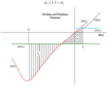
Fig 6.2 Criterial after Accidental Loss of Crane Load
ÄĚ NÌ Ń = righting moment curve at the displacement corresponding to the vessel without hook load. ÄĚ NĪ Ń = righting moment curve at the displacement corresponding to the vessel with hook load. ÀB NÌ Ń = heeling moment curve due to the heeling moment of the counter-ballast at the displace-
ment without hook load.
ÀB NĪ Ń = heeling moment curve due to the combined heeling moments of the hook load and the counter-ballast at the displacement with hook load.
ßᾚ = Limit of area integration to the downflooding angle or second intercept on the counter-bal- lasted side of the vessel.
ßᾏ =
Limit of area integration to the angle of static equilibrium due to the combined hook load and counter-ballast heeling moment.
32 Guidance for Offshore Support Vessels 2015
![]()